Diagram transformer wiring transformers circuit primary electric secondary voltage coil step core down simple basic farside utexas lectures ph teaching Transformer phase single delta wye connections connected connection transformers diagram wiring two figure power why parallel schematics electrical explained get Transformer load loading current primary between electronics voltage winding tutorials condition ideal gif phasor difference small through supply ws
Transformer Wiring Diagram Explained - Wiring Diagram and Schematic
What is an ideal transformer? circuit and phasor diagram
Transformer ideal principle diagram circuit phasor write winding figure secondary primary flux their its voltage
Circuit equivalent secondary referred parameters determination fig electricalacademiaWrite the principle of transformer? Single phase transformer connectionsThree-phase transformer connections and vector groups for beginners.
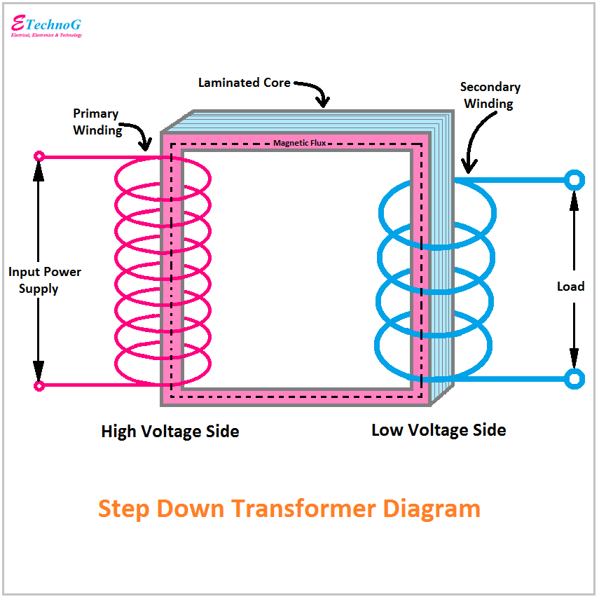
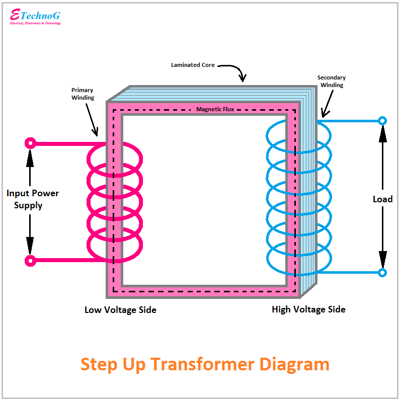
Transformer wiring diagram explainedTransformer diagram and constructional parts Determination of transformer equivalent circuit parametersTransformer ideal current electrical secondary power load action impedance coil ac working arises emf tesla.

Three phase transformer connections phasor diagrams
Transformer ratios of single-phase transformersTransformer connections phase three vector diagram schematic electrical groups secondary primary beginners turns Transformer diagram and constructional partsIdeal transformer circuit diagram.
Schematic diagram transformer welding igbt machine arc result patents inverter circuit claimsTransformer loading and on-load phasor diagrams Transformer phase diagram wye phasor lead relay electricalacademiaSave the transformers!.

Transformer phase single electrical load schematic transformers diagram figure ac connected supply symbols ratios its turns show standard power using
Transformer grounding 120v 480v isolation 240v connections technicalInductor types and symbols Transformer diagram power phase electrical single answer question draw unity constant emf factor phasor lagging leading turn per also480v to 120v 240v transformer wiring diagram.
Transformer power electrical transformers symbol schematic inductor types rf basic symbols gif find fig android electricalacademiaTransformer constructional Transformer diagram schematic.